My wife LOVES to decorate with plants. She does it on the front porch, both with big pots with nice looking plants, as well as some hanging plants on either side of the porch. She does a great job of picking stuff out, planting, and styling the whole setup.
You know what she’s not always great at? Remembering to water those plants. NJ Summers being what they are (HOT!), it’s easy to forget for a day or two and end up with plants that are gasping for life, in desperate need of a drink. That’s where I come in. Having recently had surgery and not being able to execute the 2nd half of this plan on my own, thankfully I had a bit of help from a friend. I did manage to get the first part done before my surgery though.
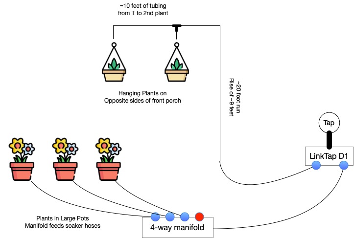
So, for the front porch, she’s got 3 big pots with plants in them, and there’s the 2 hangers flanking the porch. I ended up deciding to split this into 2 watering zones, given how differently I’d be attacking each problem.
Feeding the whole thing: LinkTap D1
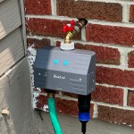
I searched and searched for the right solution. At first, I planned on doing this using Alexa Routines, as I use to automate most things. I first looked at the B-Hyve from Orbit. It didn’t expose Alexa actions, so I was stuck with mimicking Alexa voice commands in my routines. Not a big deal. The things that were a big deal to me? It didn’t stay connected reliably to our WiFi, despite being a few feet from an AP. That was one, and the second was when I called them to troubleshoot, they couldn’t understand the difference between Bluetooth and WiFi. I returned it.
I also looked at Rachio, but it was VERY hard to get ahold of at the time, so I moved on. Then I found LinkTap and went with them. I opted for their 2-zone D1 model, including the Gateway device.
LinkTap uses a Hub/Gateway model, which is of course, very common in the IOT world. The timer devices, called TapLinkers use Zigbee to talk back to the Gateway device. Setup was a snap. The app is absolutely hideous, but easy enough to work with. Setting up a schedule is pretty straight forward as well, so no complaints there.
My only complaint with LinkTap is their Alexa skill. When you invoke it to start a watering cycle, it always talks. So, when I set the routine up, every time it waters something, I’d hear “Got you. Now watering on XXXX.” Kind of annoying. Ultimately it caused me to junk the Alexa Routine for watering and break my own rule about home automation – I setup my watering routines in their app.
As a bonus, LinkTap offers a decent REST API. I haven’t done much of anything with it yet, but it’s good to know it’s there. LinkTap also has a line of valves designed for more “fixed” applications like sprinkler systems and such. Those are referred to as ValveLinkers.
Watering the Big Pots: Soaker Hoses
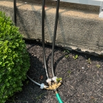
My first LinkTap zone is used for the big pots on the porch. I’m running a single leader hose from that tap out to one of those 4-way brass manifolds you can pickup at Home Depot. I’ve got 3 of the 4 taps on that open, each connected to a short feeder hose that runs to each pot. These hoses are made to custom lengths. How? I bought a 50-foot garden hose and a bunch of those repair ends for it. I cut the garden hose into the segments I needed and attached the appropriate ends. Those 3 hoses run to each of the 3 pots. In the pots themselves, I’ve got custom-length soaker hoses, built from one of those kits you can pickup in Home Depot. My wife bought one of those kits a couple of years ago, and it was just hanging out in the garage, waiting for this occasion.
Watering the Hanging Pots: Drip Irrigation
This was my first foray into drip irrigation, so I had a bit of read-up to do in order to figure out what I needed to buy to do the job right. Turns out that it was super easy to get it done. Water pressure is important, so I started with a pressure regulator, followed by an adapter to drop down from the usual 3/4″ garden hose fitting down to 1/4″ tubing.
As for tubing, I opted for polyethylene tubing, as it’s a bit more durable than PVC, though a bit less flexible than PVC. I felt the trade-off was worth it though. From the LinkTap to the porch itself, I used black tubing, held in place on the ground using those “staples” you use to hold landscape fabric down. When we reached the post we were going to run up to the top of the porch, we inserted an elbow and changed to white tubing, which we secured to the post using those U-shaped clips you see cable tv installers use to secure coax to baseboards. I had a bunch of those laying around, so nothing left to buy.
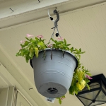
At the top of the porch, we used a T-fitting to split the runs to the 2 hanging plants, included a shut-off valve for each plant, and finally the drippers above each plant. You can see the shut-off valve and the dripper in the image just above!
I wouldn’t have been able to get this part done without the help of my good friend John, so thanks!
How it all Fits Together
The Shopping Lists
The Timer
| Product | Link |
|---|---|
| LinkTap D1 with Gateway | https://www.amazon.com/dp/B0B3DZHHXL |
The Porch Pots – Soaker Hoses
| Product | Link |
|---|---|
| 50-foot Garden Hose | https://www.homedepot.com/p/100022734 |
| Hose Repair Ends | https://www.amazon.com/dp/B0C6SX8B4S |
| 4-way Hose Manifold | https://www.homedepot.com/p/303652362 |
| Soaker Hose Kit | https://www.homedepot.com/p/310333284 |
The Hanging Pots – Drip Irrigation
| Product | Link |
|---|---|
| Rain Bird Pressure Regulator | https://www.amazon.com/dp/B0049C5FZA |
| Rain Bird 1/4″ Tubing Adapter | https://www.amazon.com/dp/B000BQU75Q |
| Rain Bird 1/4″ White Poly Tubing | https://www.amazon.com/dp/B000BO6QUI |
| Rain Bird 1/4″ Black Poly Tubing | https://www.amazon.com/dp/B008RH61SS |
| Rain Bird 1/4″ T-Fittings | https://www.amazon.com/dp/B000AQG9LS |
| Rain Bird 1/4″ Elbow Fittings | https://www.amazon.com/dp/B000AQG9KY |
| Rain Bird 1/4″ Shut-Off Valves | https://www.amazon.com/dp/B00NOA4NOW |
| Axe Sickle Adjustable 1/4″ Drippers | https://www.amazon.com/dp/B087WRYQ3K |

You must be logged in to post a comment.